"110V" really means 110V
Long story short: I’ve been to the US a few weeks ago and I thought I’d pick up a new Xbox 360 250GB while I was there, seeing as those are hard to find in China. I assumed its power supply would accept both 110V and 220V (like my PS3 and most modern PCs and laptops.) Well, it did not.
Of course, I did not just plug it in and watch explode. I first opened up the power supply (not an easy feat, let me tell you) and only plugged it in after noticing the board inside had “250V” written on it, with a check mark next to it. Not sure what that meant though. It still blew up after I plugged it in.
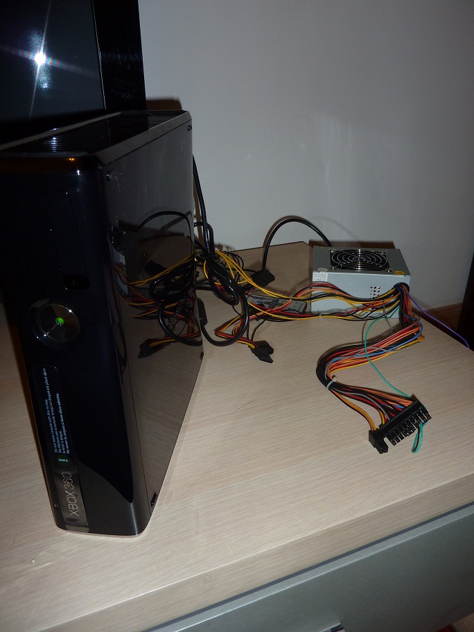
I already had a plan B from the moment I bought the Xbox: the power supply output 12V and 5V, much like a regular PC power supply. So I bought a (mini) ATX power supply and went online to see if I could find the pinout. Plenty. When I plugged in the ATX power source, I measured the voltage on a few pins, but got nothing. Then I remembered the fact that an ATX power supply does not really turn on until the PC tells it to. This is done by shorting pin 14 of the ATX plug (green wire) to ground (black, any will do.) Once I did that, I got all the power I needed.
The pinout on the Xbox side was harder to come by. I had found a few for the old Xbox 360, but none for the new slim model. Fortunately there were some hints on the PSU’s board:
Yellow 12V
Black GND
Red 5VSB
Blue PS_ON
Gray RSENSE
I thought I’d check what I could get away with: I connected the yellow wire from the Xbox to the yellow wire of the PSU. Same for the red wires, and black wires, matching the colors. Then, I turned on the power supply by connecting the green wire on pin 14 to a black wire. I pressed the button on the Xbox: success!
 Having the power supply turned on all the time was not something I liked though. So the next step was to get the power supply to turn on together with the Xbox. By measuring the voltage I saw the blue PS_ON wire being pulled up (~3.3V) when the Xbox wants to turn on. In order to do this, the Xbox needs some power though. This is done by the red “5VSB” wire. The “SB” stands for Stand By. This means that the red wire from the Xbox must not be attached to the red ATX wires, but to the purple wire on pin 9.
This page explained how: use a transistor or optocoupler that will connect the green ATX wire to GND when the blue Xbox wire goes up. I had no optocoupler lying around, or so I thought. I then noticed the blown up power supply on the table. There were some things on it that looked a lot like optocouplers. Sure enough:
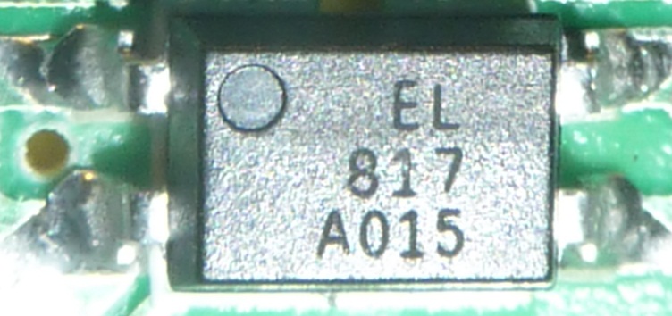 The datasheet for the EL817 can be found here.
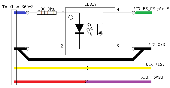
So, pin 1 of the optocoupler (the pin near the dot) will be pulled high, to ~3.3V. We want to give the LED inside about ~1.2V, that leaves 2.1V for a resistor. At about 20mA this means we need a V/I=R 2.1/0.02= ~100 Ohm resistor. 100 Ohm = 10*10, 10 times 10 to the power 1: we need a resistor with Brown, Black, Brown rings. Luckily I found one 
I had everything I needed:
Yellow (Xbox) - Yellow (ATX)
Red (Xbox) - Purple (ATX)
Blue (Xbox) - Resistor - Optocoupler pin 1
Black (Xbox) - Black (ATX)
Optocoupler pin 2 - Black (ATX)
Optocoupler pin 3 - Black (ATX)
Optocoupler pin 4 - Green (ATX)
Gray (Xbox) - unused
I had no idea what the gray RSENSE wire was for, so I just ignored it and it worked fine! Once I got everything figured out, I opened up the ATX PSU and removed all the wires I didn’t use. Important: there was a brown wire that got connected to a orange (3.3V) wire IN the ATX power connector. So after cutting of the connector I had to connect the brown wire to 3.3V somewhere inside the PSU.
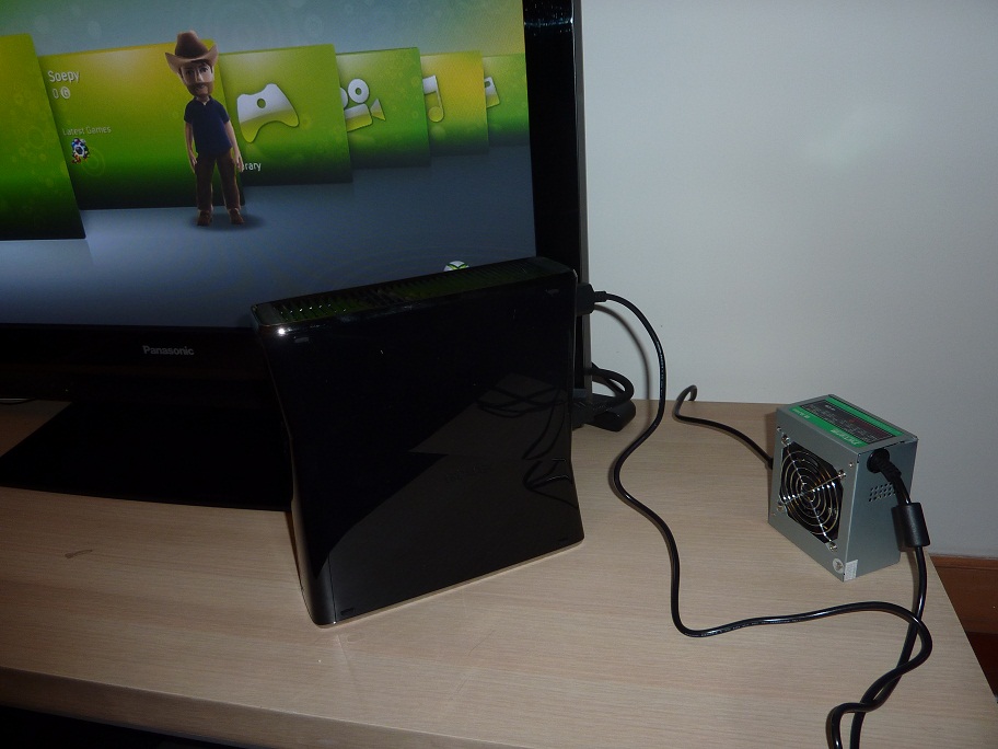 And all it cost me was an ATX power supply and 1 blister. Not bad
UPDATE: Here’s the schematic for the whole thing: